It was huge news earlier this year: the first patient in the world, an infant, was successfully treated with a CRISPR gene editing therapy personalized to his genetic mutation. “Baby KJ” was diagnosed with a rare and dangerous metabolic disease shortly after his birth. Within a ...
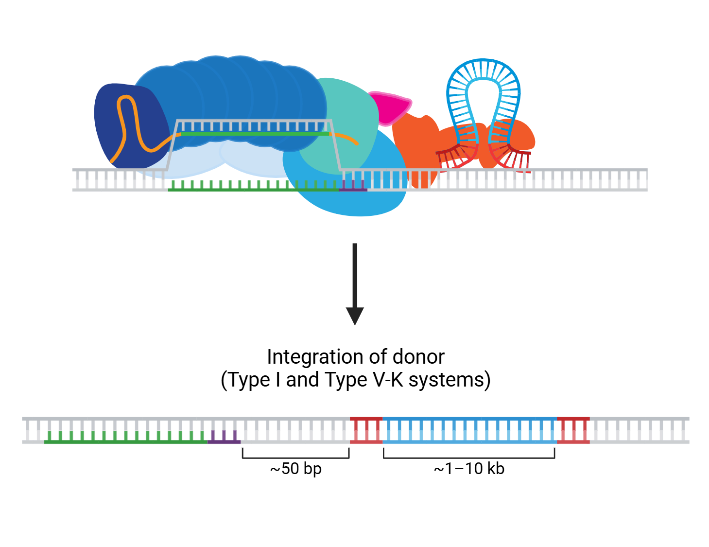
These days, it hardly seems like we finish writing about one dual CRISPR-transposon system before another exciting new advance emerges! The programmability and targeting power of CRISPR combined with the large sequence capacity of transposons open whole new worlds to explore. ...
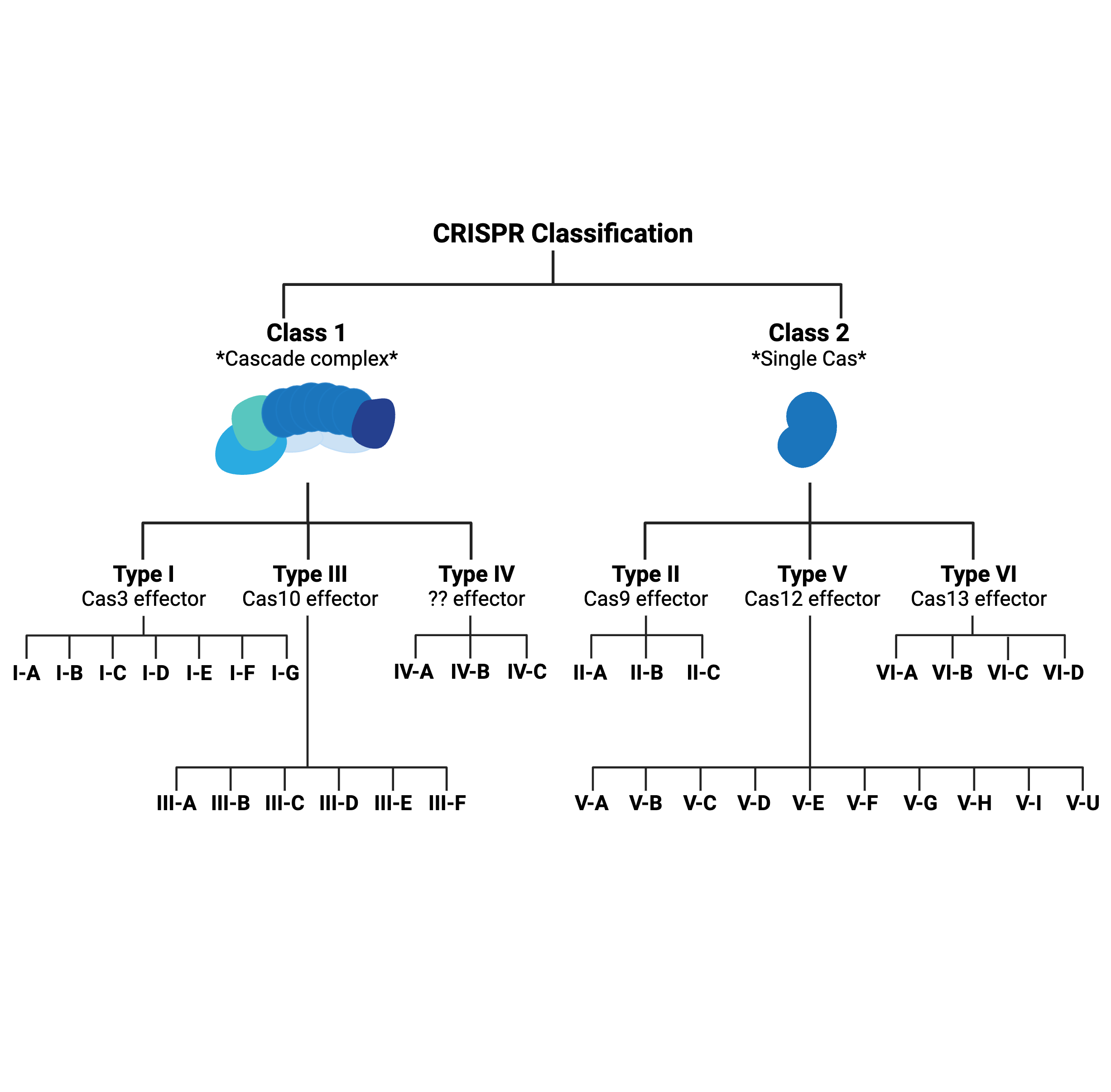
What’s in a type? That which we call CRISPR, by any other name would…probably still edit genomes.
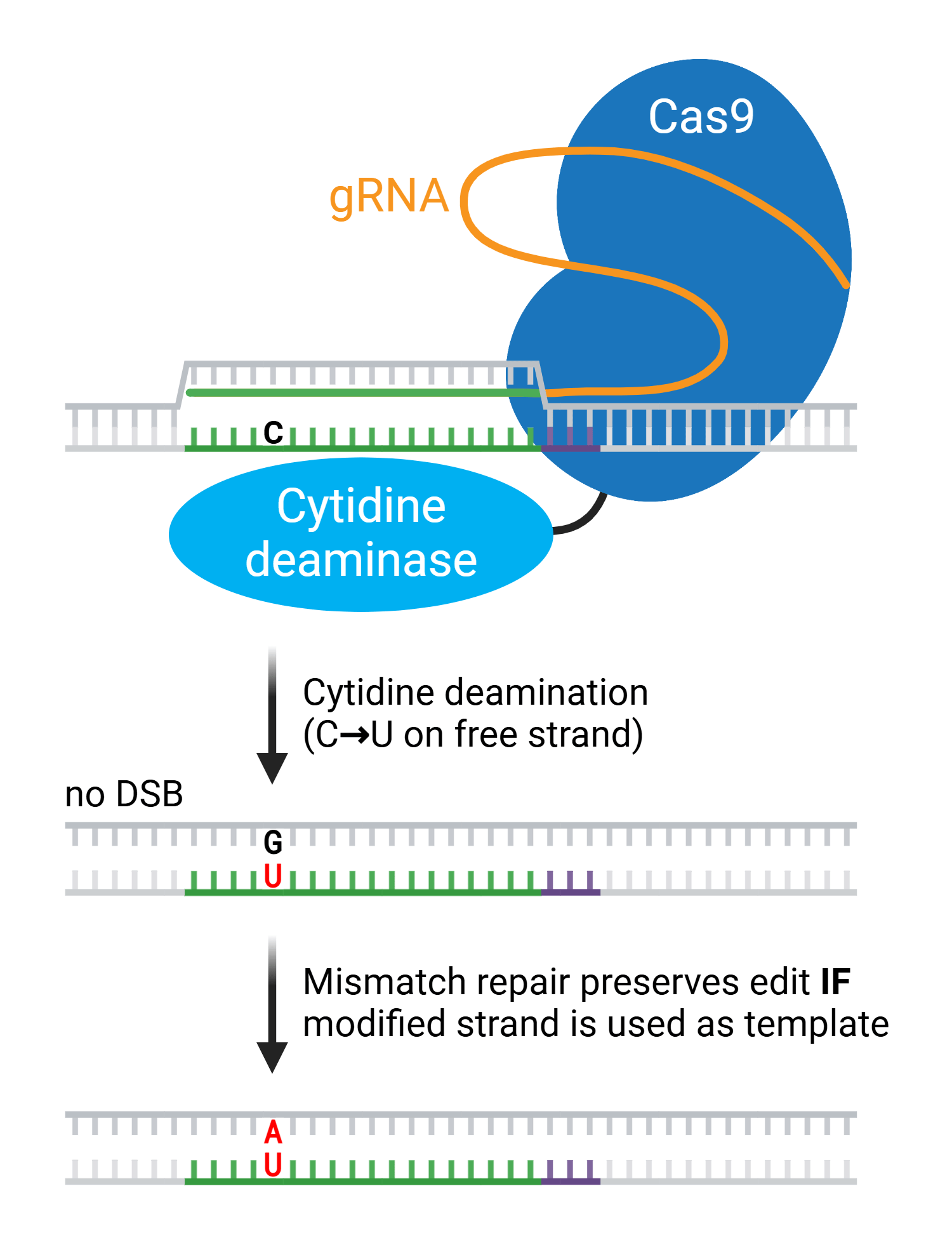
Early CRISPR applications were often limited by the low editing efficiency of homology-directed repair (HDR), the pathway for resolving DNA double-strand breaks (DSBs) preferred by researchers. Compared to non-homologous end joining (NHEJ), HDR occurs at a relatively low ...
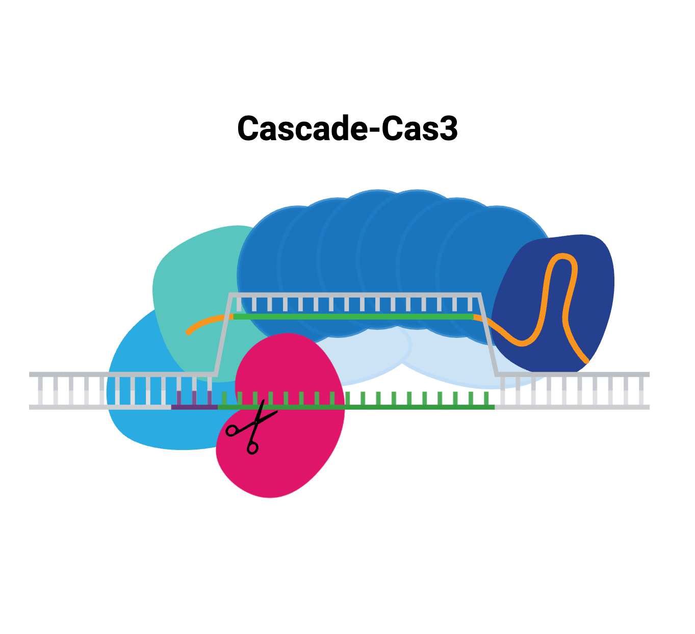
The versatility of CRISPR allows you to play with DNA in a number of ways, from small edits that change single base pairs, to chromosomal inversions and large deletions. Many of these methods rely on Cas9 or a derivative of Cas9, but the ever-expanding repertoire of CRISPR has ...
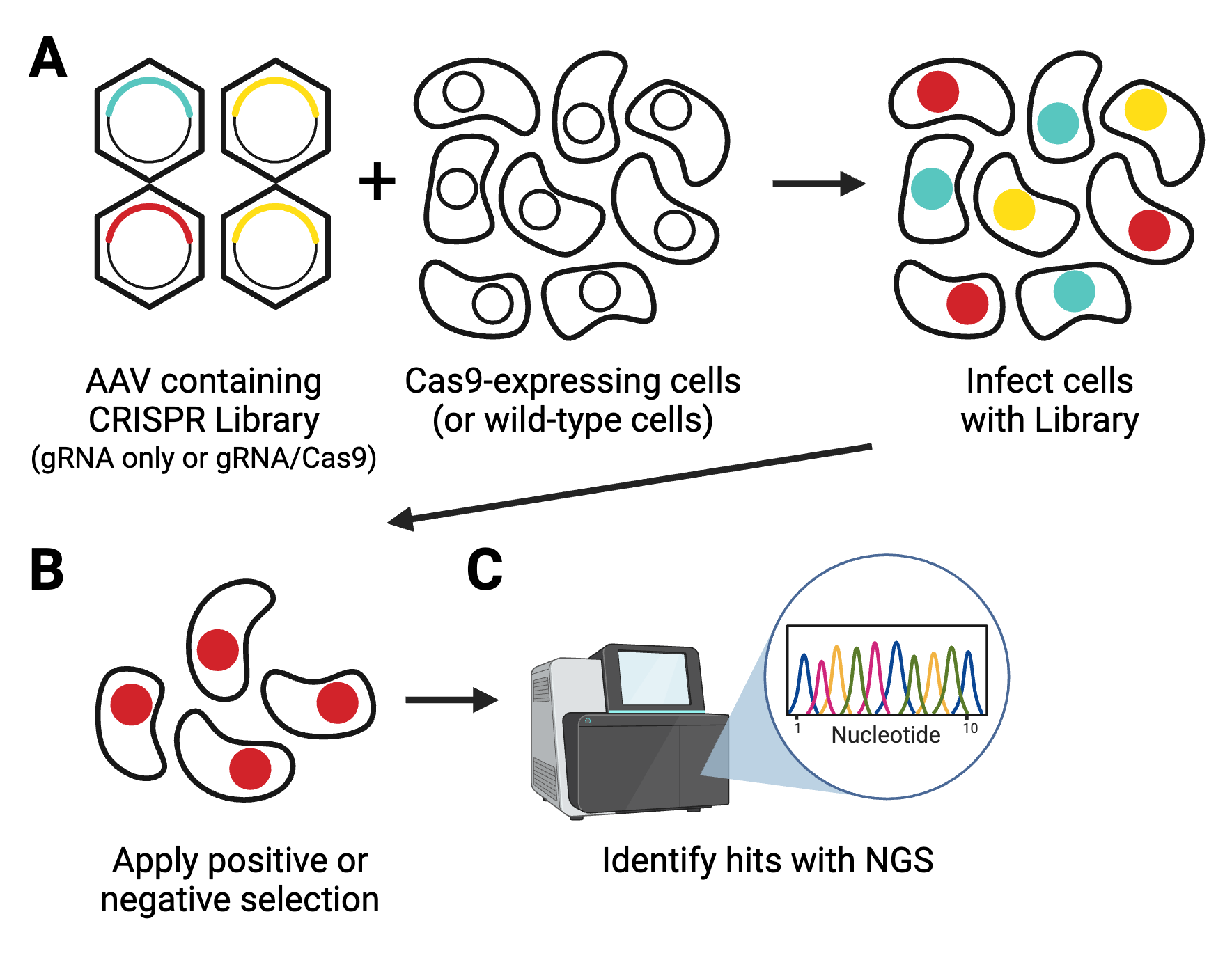
Forward genetics screens are a valuable part of the molecular biology toolbox to identify new target genes for drug discovery or to understand the intricacies of molecular pathways. These screens have gotten larger, easier, and more comprehensive thanks to the consistent ...
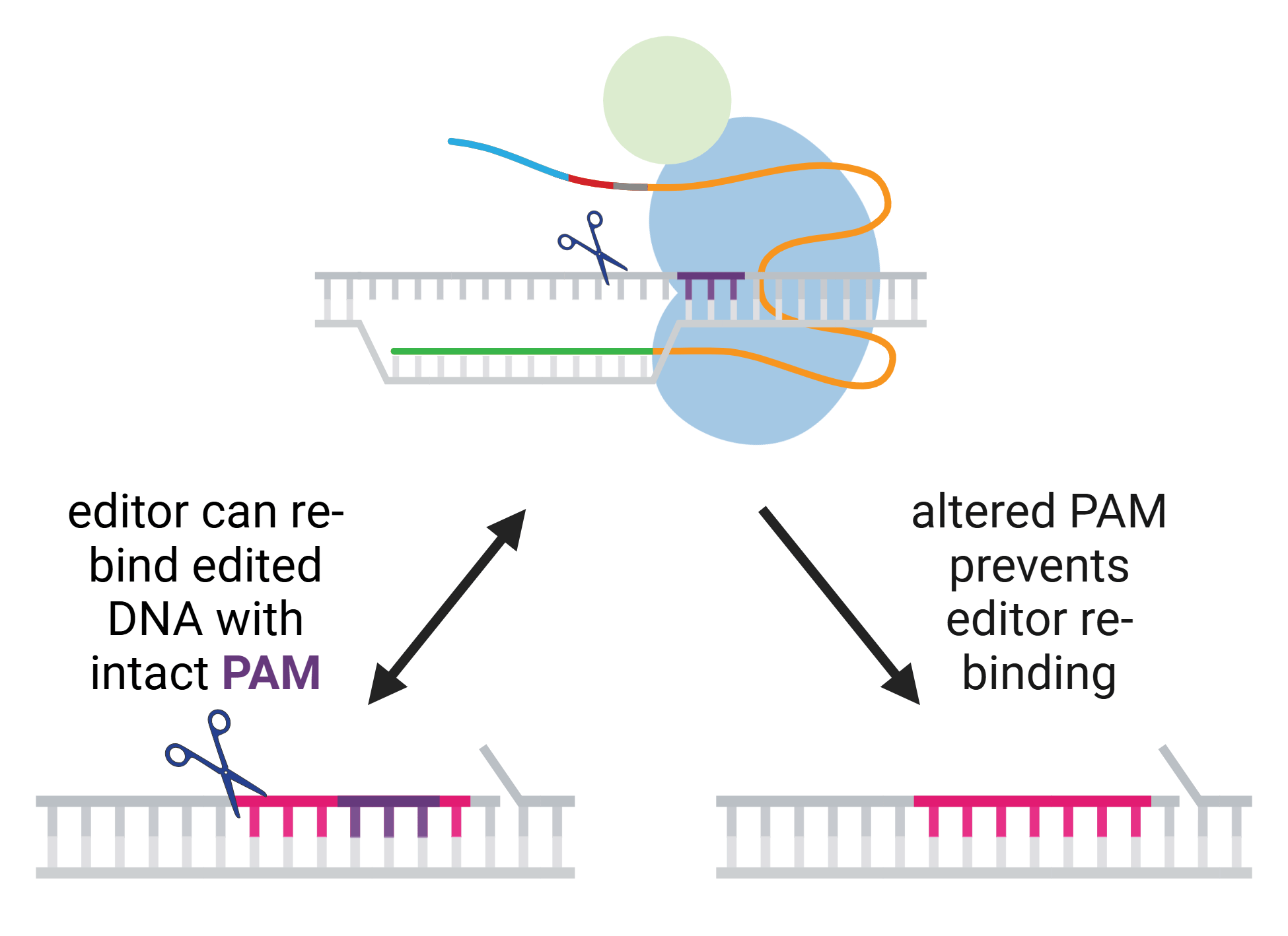
We recently updated our blog post on Prime Editing, and that meant rereading many of the original papers reporting various prime editing tools. These papers are chock full of great tips to guide your experimental design, especially the design of the RNA sequences you’ll use in ...
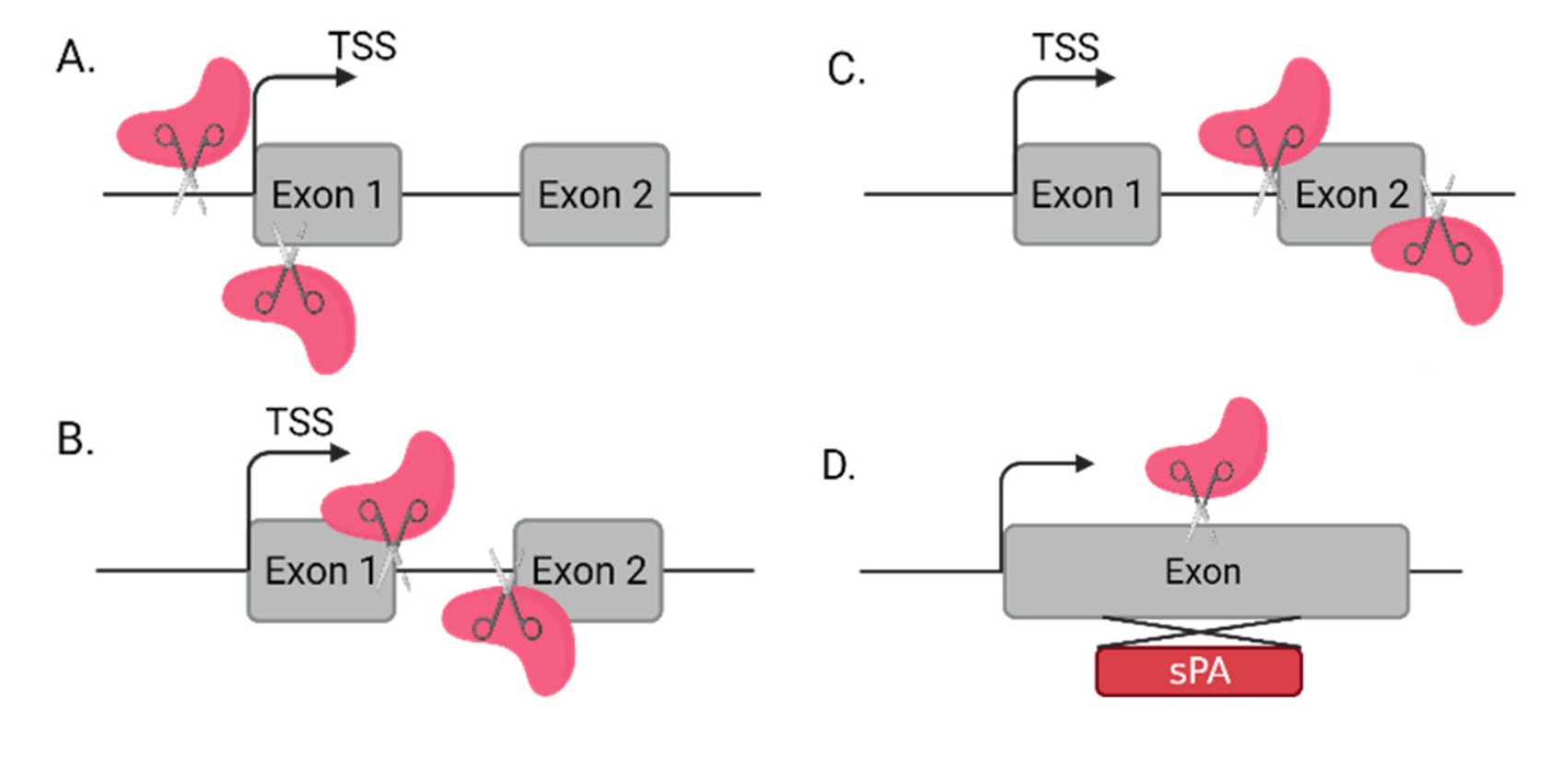
You’ve probably heard that only 2% of our genome is made of protein-coding genes, and you might be wondering what the rest of our genome could possibly be made up of. The answer is… drum roll please… non-coding RNAs! You probably didn’t see that coming, right? Non-coding RNAs ...