iGEM isn’t any old science fair. “The world’s biggest synthetic biology competition” brings together hundreds of student teams to build projects and solve problems using molecular biology.
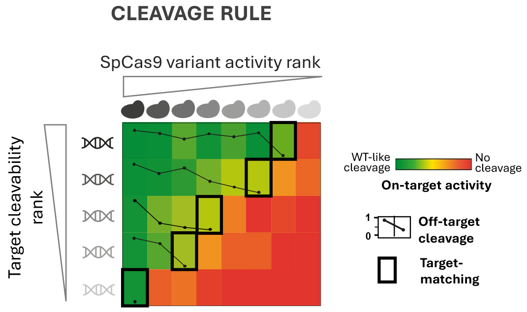
ByBalázs Csoma, Hungarian Research Network CRISPR nucleases are remarkably precise molecular tools for cutting DNA. But “remarkably precise” does not mean “perfectly specific.” In reality, CRISPR nucleases occasionally make mistakes and cleave DNA sequences that only resemble ...
Deaminet 2026, held in Palm Springs in late January, brought together researchers studying deaminase enzymes across disciplines: from structural biologists resolving APOBEC proteins at atomic resolution, to cancer biologists dissecting mutational processes, to medical ...
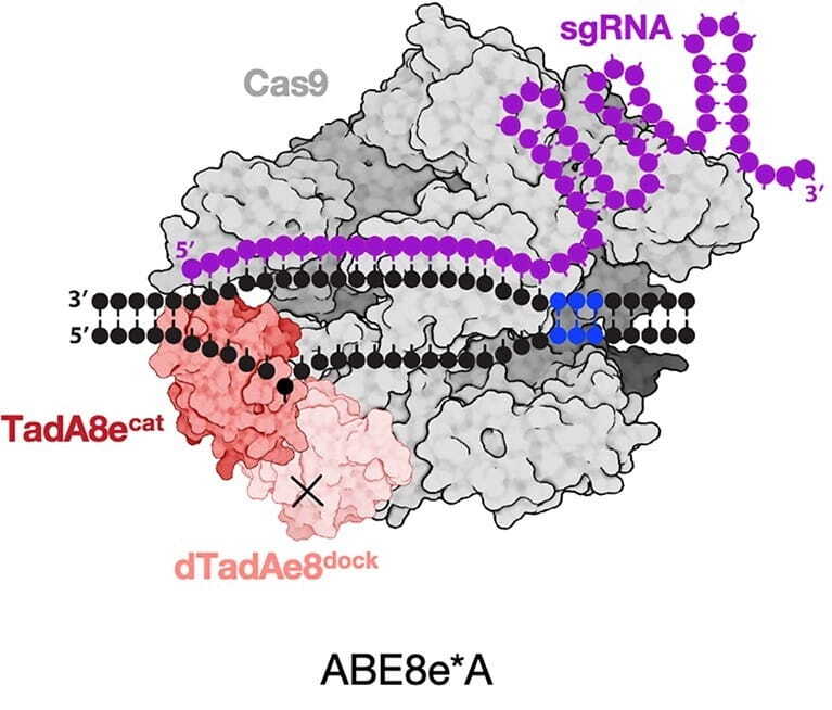
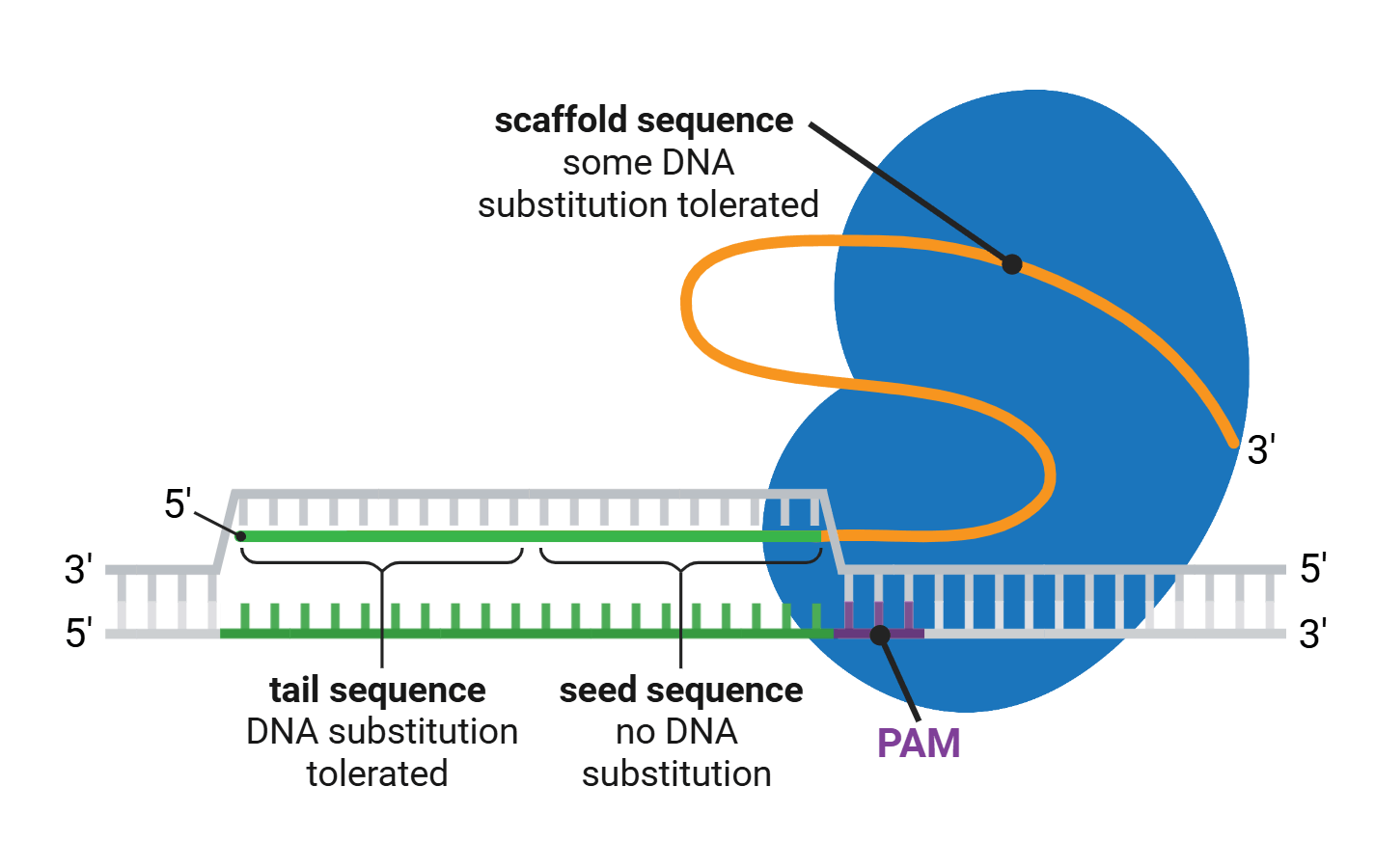
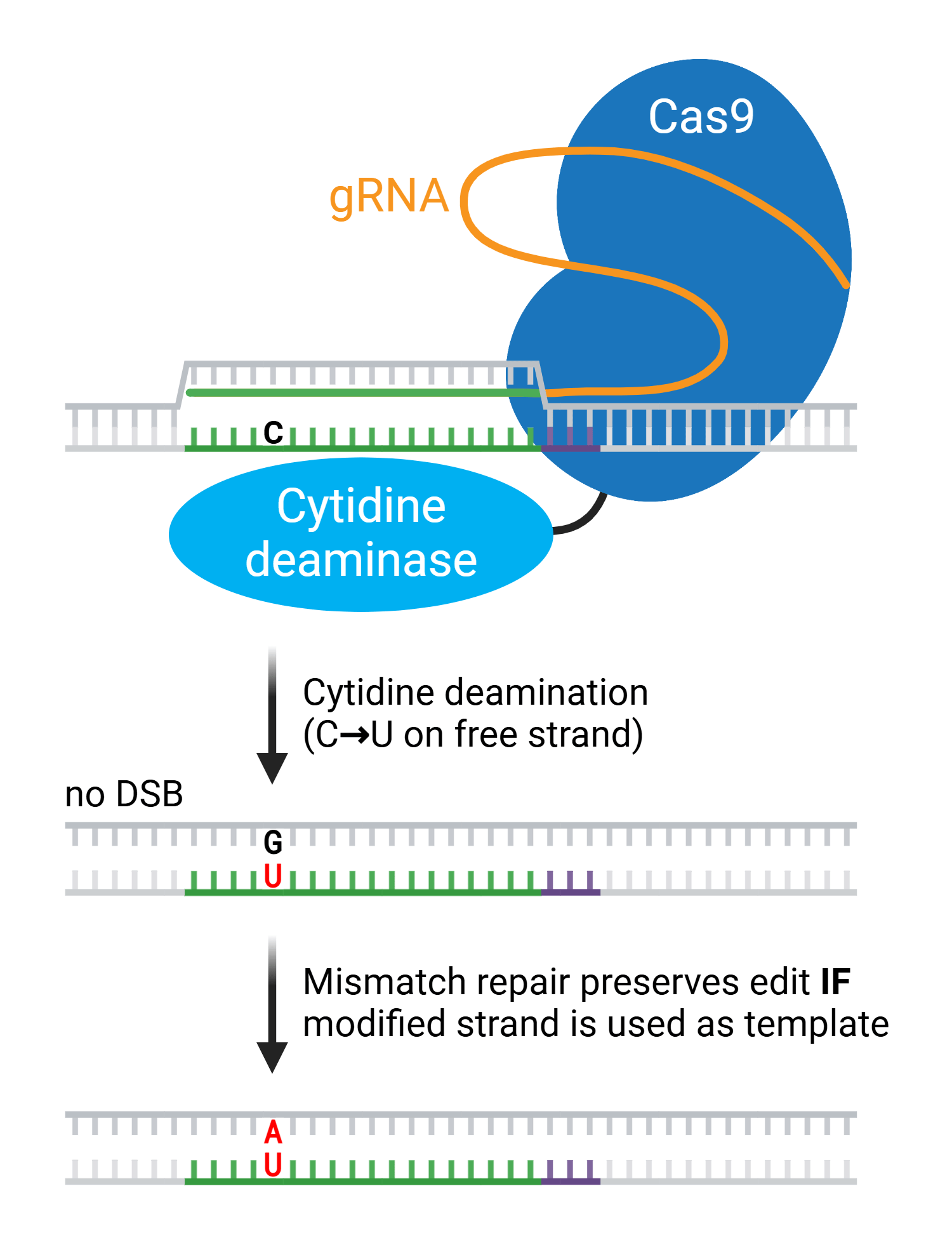
The genome-editing tool CRISPR is famously RNA-guided... except when it’s not. Turns out, carefully designed RNA-DNA hybrid strands work just as well—or maybe even better—at guiding Cas nucleases to specific genomic targets.
It was huge news earlier this year: the first patient in the world, an infant, was successfully treated with a CRISPR gene editing therapy personalized to his genetic mutation. “Baby KJ” was diagnosed with a rare and dangerous metabolic disease shortly after his birth. Within a ...
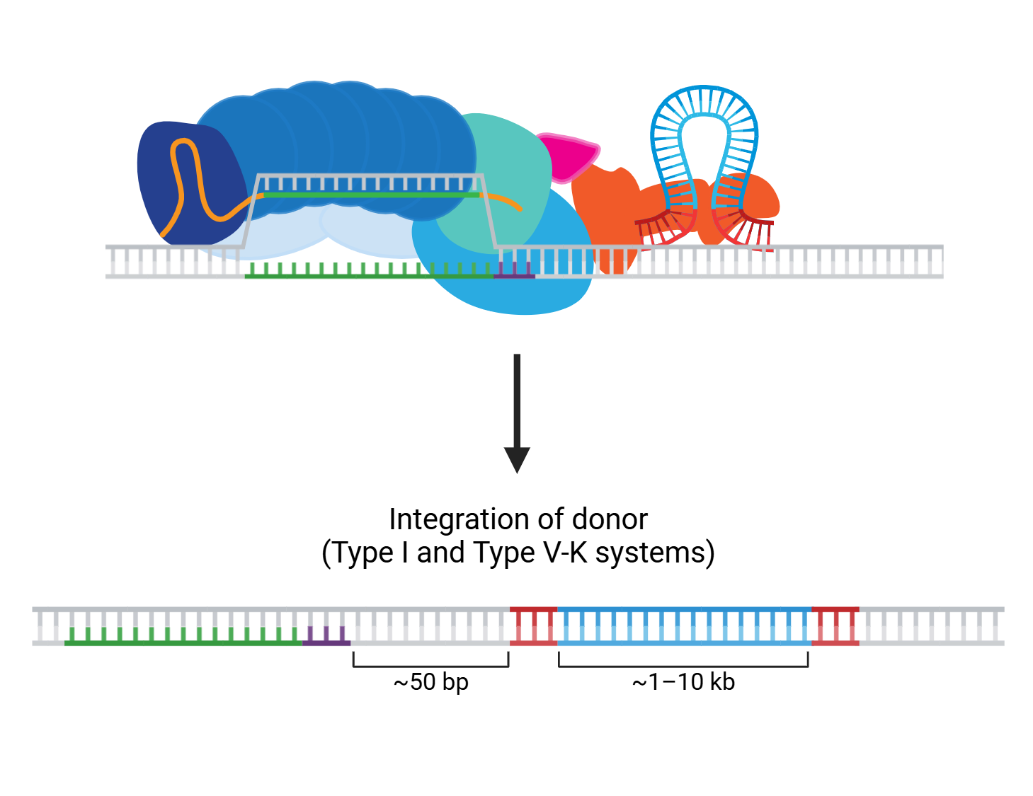
These days, it hardly seems like we finish writing about one dual CRISPR-transposon system before another exciting new advance emerges! The programmability and targeting power of CRISPR combined with the large sequence capacity of transposons open whole new worlds to explore. ...
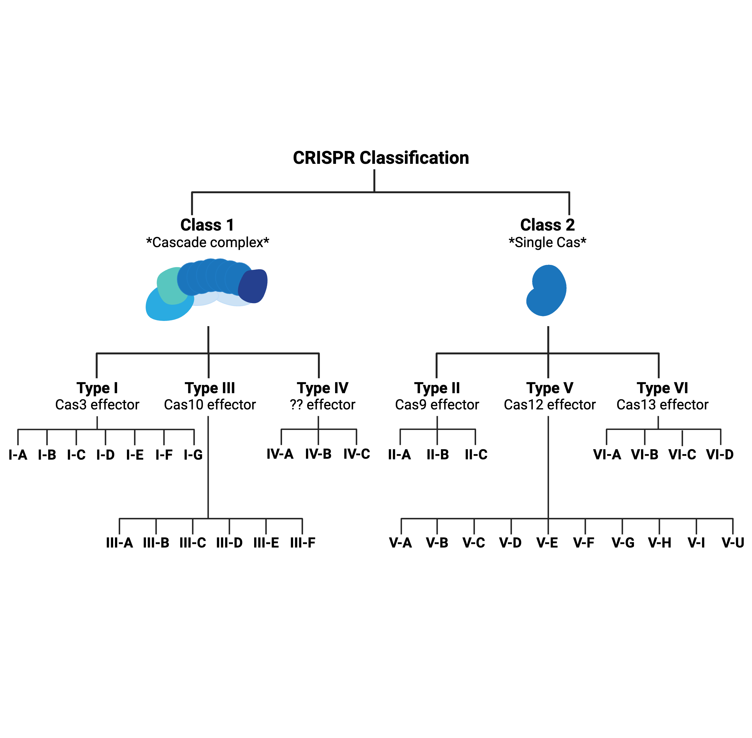
What’s in a type? That which we call CRISPR, by any other name would…probably still edit genomes.
Early CRISPR applications were often limited by the low editing efficiency of homology-directed repair (HDR), the pathway for resolving DNA double-strand breaks (DSBs) preferred by researchers. Compared to non-homologous end joining (NHEJ), HDR occurs at a relatively low ...